X-ray fluorescence (XRF) spectroscopy is increasingly the analytical tool of choice for the direct measurement of the concentration of atomic elements in a wide range of materials. From solids and powders to liquids and thin films, XRF has become an ever more powerful quantitative technique thanks to ongoing evolutionary developments and revolutionary breakthroughs in X-ray source, optic and detector technologies.
From the introduction of commercial wavelength dispersive XRF spectrometers in the mid-1950s, to the development of energy dispersive X-ray fluorescence (EDXRF) instruments in the early 1970’s, the increasing availability of affordable computational power was critical to the desirability and acceptance of the technique. With the widespread availability and use of the personal computer (PC) as the industry standard platform in the mid-1980s, X-ray fluorescence spectroscopy became a simplier and lower cost-of-ownership alternative to earlier atomic spectroscopy analytical techniques.
X-ray fluorescence theory
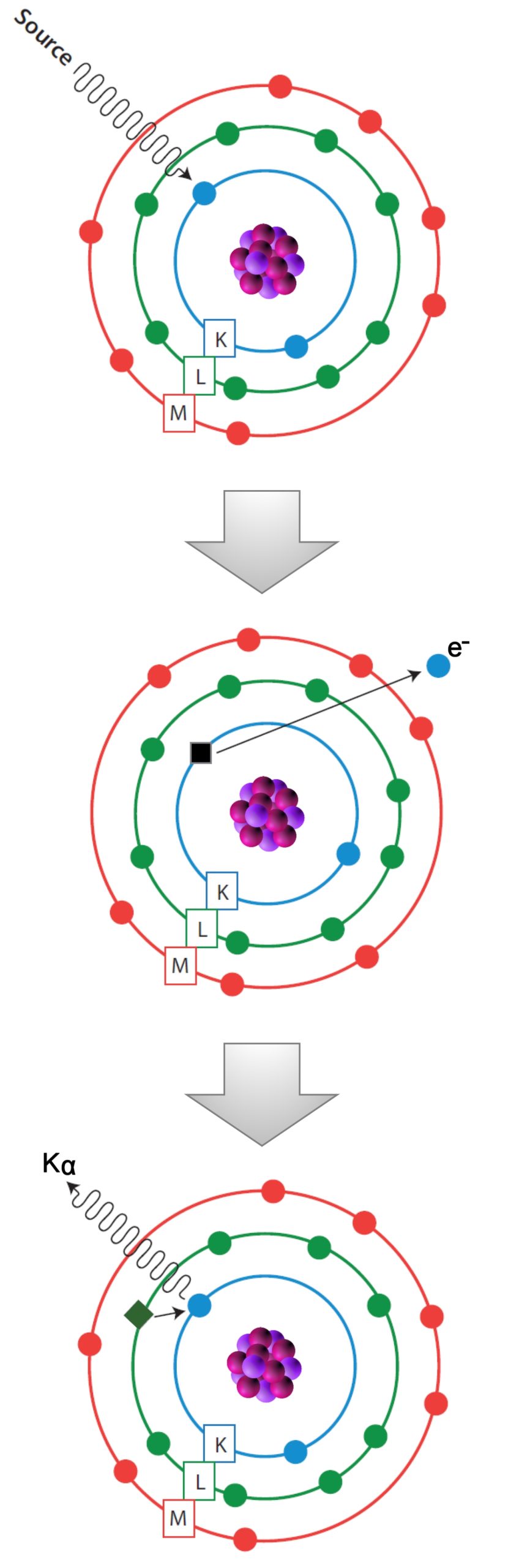
In X-ray fluorescence (XRF), an electron can be ejected from its atomic orbital by the absorption of a light wave (photon) of sufficient energy. The energy of the photon (hν) must be greater than the energy with which the electron is bound to the nucleus of the atom. When an inner orbital electron is ejected from an atom (middle image), an electron from a higher energy level orbital will be transferred to the lower energy level orbital. During this transition a photon maybe emitted from the atom (bottom image). This fluorescent light is called the characteristic X-ray of the element. The energy of the emitted photon will be equal to the difference in energies between the two orbitals occupied by the electron making the transition. Because the energy difference between two specific orbital shells, in a given element, is always the same (i.e. characteristic of a particular element), the photon emitted when an electron moves between these two levels, will always have the same energy. Therefore, by determining the energy (wavelength) of the X-ray light (photon) emitted by a particular element, it is possible to determine the identity of that element.
For a particular energy (wavelength) of fluorescent light emitted by an element, the number of photons per unit time (generally referred to as peak intensity or count rate) is related to the amount of that analyte in the sample. The counting rates for all detectable elements within a sample are usually calculated by counting, for a set amount of time, the number of photons that are detected for the various analytes’ characteristic X-ray energy lines. It is important to note that these fluorescent lines are actually observed as peaks with a semi-Gaussian distribution because of the imperfect resolution of modern detector technology. Therefore, by determining the energy of the X-ray peaks in a sample’s spectrum, and by calculating the count rate of the various elemental peaks, it is possible to qualitatively establish the elemental composition of the samples and to quantitatively measure the concentration of these elements.
X-ray tube excitation
Like the formerly common vacuum tubes, X-ray tubes are comprised of a cathode – which emits electrons into the vacuum – and an anode to collect the electrons, thus establishing a flow of electrical current through the tube. A high voltage power source, for example 4 to 150 kilovolts (kV), is connected across cathode and anode to accelerate the electrons to impact the anode. The X-ray spectral output of an X-ray tube, which includes both characteristic lines from the anode material and Bremsstrahlung (braking) radiation, depends on the anode material and the accelerating voltage.
SDD EDS detectors
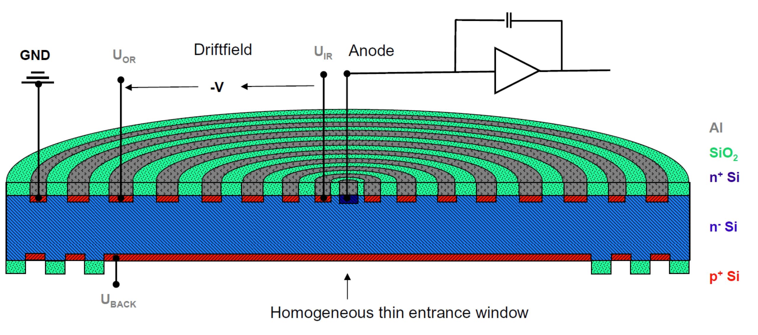
A new category of Peltier cooled X-ray detectors, silicon drift detectors (SDD), are chiefly used for energy dispersive X-ray fluorescence (EDXRF) spectrometry as well as for energy dispersive spectrometry (EDS) within electron microscopy. This technology has become very popular because their characteristics, compared with other X-ray detectors, include very high count rates and comparatively high energy resolution. Like other solid state X-ray detectors, silicon drift detectors measure the energy of an incoming photon by the amount of ionization it produces in the detector material. The major distinguishing feature of an SDD is a transversal field generated by a series of ring electrodes that forces charge carriers to ‘drift’ to a small collection electrode. This ‘drift’ concept of the SDD allows for throughput beyond 100,000 counts per second (CPS). Current generation SDD EDXRF detectors, with the field effect transistor (FET) moved out of the radiation path, are far more reliable than the first generation devices and represent the current state-of-the-art in conventional EDXRF detector technology.
Pulse processor and multi channel analyzer
Pulses generated by high resolution X-ray detector are processed by pulse-shaping amplifiers (pulse processor). As it takes time for the amplifier to shape the pulse for optimum resolution, there is necessarily a trade-off between resolution and count-rate. Long processing times deliver better resolution but can result in “pulse pile-up” in which the pulses from successive photons overlap. Current state-of-the-art digital pulse processing techniques rely on linear filtering methods which attempt to reduce the pulse length to improve detector performance. However the inability to resolve closely spaced pulses means pulse pile-up remains a problem. This results in limited detector throughput, decreased spectral accuracy and energy resolution, increased spectral noise, and detector dead time. In EDXRF, the multichannel analyzer (MCA) is the component used to store information from the pulse processor. Each channel corresponds to a small energy increment and each pulse from the detector is stored in the appropriate channel according to the amplitude of the pulse (that is, the photon energy).
Applications
EDXRF spectrometers are the elemental analysis tool of choice, for many applications, in that they are smaller, simpler in design and cost less to operate than other technologies like inductively coupled plasma optical emission spectroscopy (ICP-OES) and atomic absorption (AA) or atomic fluorescence (AF) spectroscopy. Examples of some common EDXRF applications are: