MicroXRF for Materials Characterization and Alloy Analysis
Atlas Apex is a laboratory microXRF alloy analyzer designed to map elemental composition across alloys, coatings, welds, fracture surfaces, ceramics, composites, and additively manufactured materials.
Unlike bulk techniques that report only average composition, microXRF shows where elements are located and how their distribution relates to segregation, contamination, corrosion, coating variation, and material failure.
With focused-beam analysis, automated large-area mapping, and full-spectrum data at every pixel, Atlas Apex connects localized chemical features with the structure of the complete sample — often with little or no destructive preparation.
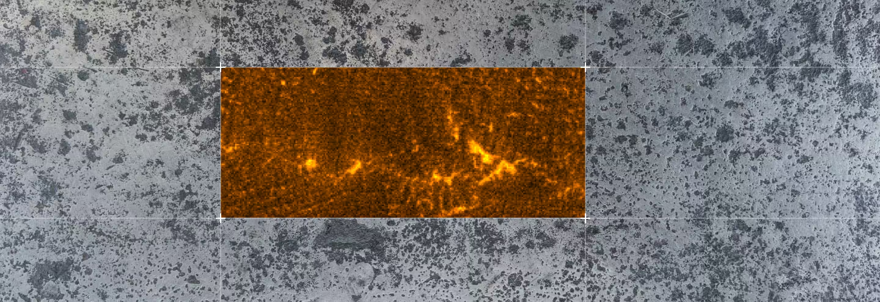
Why Use MicroXRF for Materials Characterization?
Most samples can be analyzed without chemical digestion, spark ablation, or a conductive coating.

Traditional bulk measurements provide an average composition.
MicroXRF adds the spatial information needed to understand segregation, contamination, coating variation, corrosion, and localized failure.
- Elemental distribution matters as much as average composition
- The sample must remain intact
- The part is large, heavy, non-conductive, or irregularly shaped
- Minimal sample preparation is preferred
- A full component, weld, coating, or cross-section must be mapped
- Researchers need to locate regions for detailed follow-up analysis
Materials Science Applications
Alloy Composition and Segregation Mapping
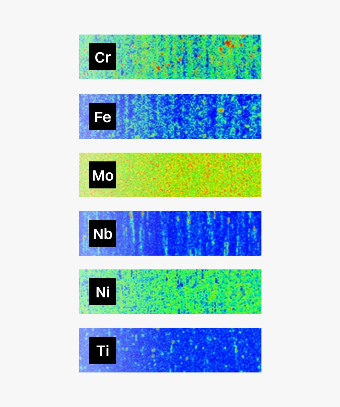
Alloy certificates and bulk measurements confirm average chemistry, but they may not reveal localized compositional variation. MicroXRF maps alloying elements across castings, welds, billets, slabs, and finished parts to identify patterns such as:
- Chromium and nickel banding in stainless steel
- Dendritic segregation in nickel-based superalloys
- Centerline segregation in continuously cast steel
- Localized depletion or enrichment of alloying elements
- Compositional differences between weld metal, heat-affected zones, and base material
- Metallic contamination introduced during processing
For at-line centerline segregation measurements in steel production, IXRF also offers the ProSA process XRF analyzer.
Coatings and Thin Films
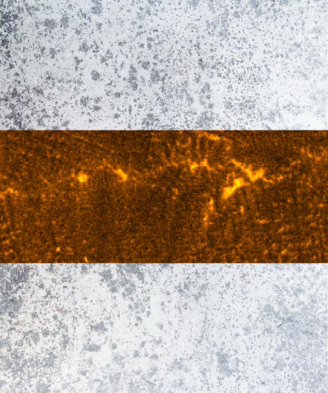
Coating performance depends on more than nominal composition. Uniformity, thickness, contamination, and local defects can all affect the behavior of the finished component. MicroXRF can evaluate coating composition across an entire part rather than relying on a limited number of spot measurements.
Common applications include:
- Thermal barrier coatings
- Hard chrome and electroplated coatings
- Corrosion-resistant coatings
- PVD and CVD films
- Multilayer coatings
- Graded material systems
Failure Analysis
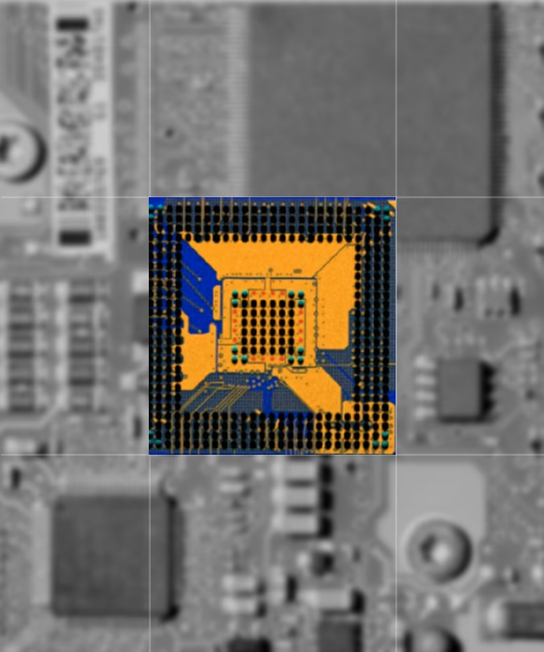
Failure analysis often begins with a localized question: what caused the crack, deposit, corrosion pit, or unexpected fracture? MicroXRF can map an entire damaged component or fracture surface without immediately cutting or altering the sample — especially valuable when the part is expensive, irreplaceable, customer-owned, or retained as evidence. Elemental maps can help identify:
- Inclusion chemistry near a crack origin
- Corrosion products and deposits
- Unexpected metallic contamination
- Material transfer between contacting surfaces
- Coating degradation
- Chemical differences across a failed weld
- Residues associated with overheating or chemical exposure
Additive Manufacturing Characterization
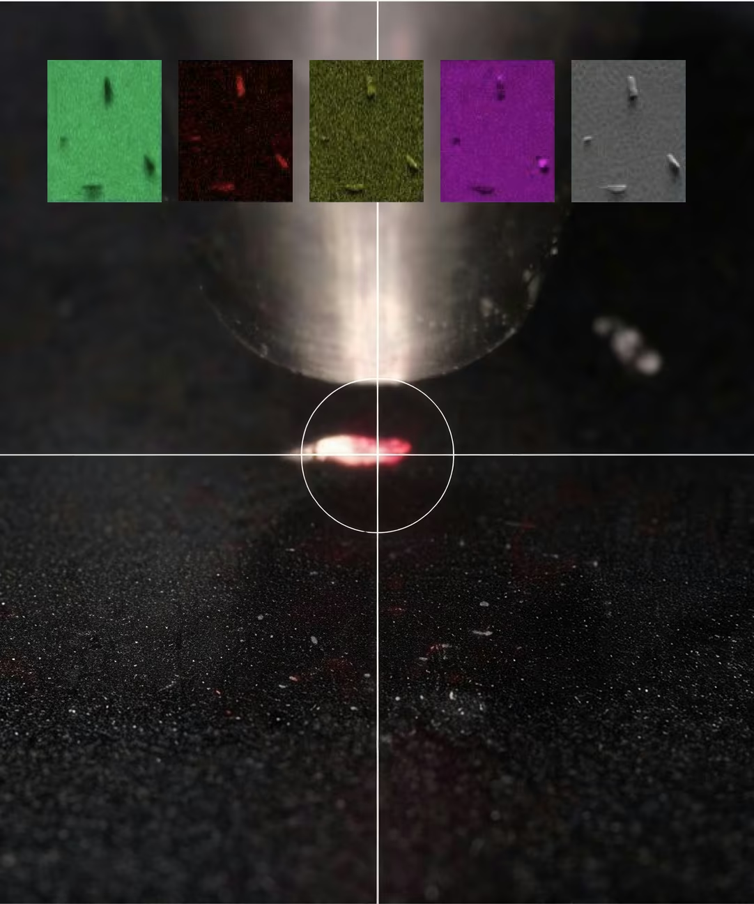
Additively manufactured materials can contain localized chemical variations that are difficult to identify using bulk analysis alone.
MicroXRF can map powder samples, build layers, coupons, and full part cross-sections to investigate:
- Powder feedstock contamination
- Compositional consistency across a build
- Elemental segregation near pores or melt-pool boundaries
- Multi-material structures
- Functionally graded materials
- Relationships between print parameters and elemental distribution
Ceramics and Composites
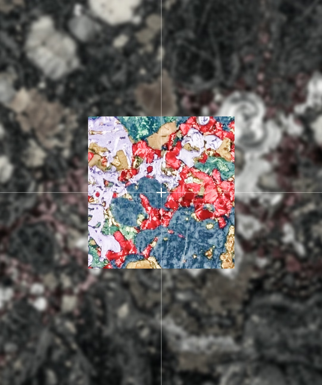
Ceramics and composite materials often contain phases, reinforcements, fillers, or dopants with different elemental signatures.
MicroXRF can show how these components are distributed across a relatively large area, supporting the evaluation of:
- Reinforcement placement
- Filler distribution
- Dopant uniformity
- Secondary phases
- Inclusions and contamination
- Interfaces between dissimilar materials
Aerospace and Automotive Materials
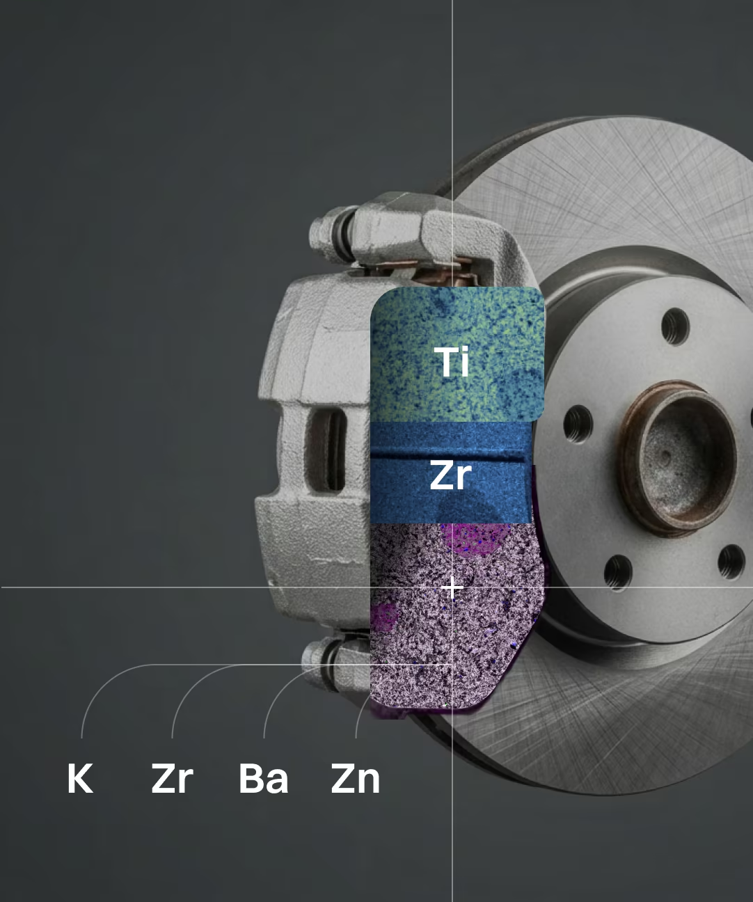
Aerospace and automotive components frequently combine complex alloys, protective coatings, welds, and engineered surfaces.
MicroXRF supports the non-destructive examination of:
- Nickel and cobalt superalloys
- Aluminum and titanium alloys
- Welds and brazed joints
- Thermal barrier coatings
- Corrosion-resistant surfaces
- Deposits and foreign material
- Fracture surfaces
- Additively manufactured parts
How the MicroXRF Measurement Works
Atlas Apex directs a focused X-ray beam onto the sample. The illuminated atoms emit characteristic X-rays that identify the elements present. As the sample moves beneath the beam, the system creates elemental maps showing where each element is located.
Minimal Sample Preparation
Most materials science samples can be analyzed without conductive coating, chemical digestion, or spark preparation. Large parts, polished sections, fracture surfaces, ceramics, coatings, powders, and irregularly shaped components can often be measured directly.
Focused-Beam Analysis
Available X-ray source and optic configurations provide focused spot sizes down to approximately 5 µm, allowing researchers to investigate:
- Coating boundaries
- Segregation bands
- Large inclusions
- Deposits
- Corrosion features
- Localized contamination
Large-Area Elemental Mapping
Automated stages allow Atlas Apex systems to map large components, welds, cross-sections, and assemblies — a broader view than isolated spot measurements, connecting localized chemistry with the complete sample structure.
Hyperspectral Data at Every Pixel
Atlas Apex stores a complete X-ray spectrum at every mapped pixel. Researchers can generate maps for additional elements, revisit the dataset without rescanning, compare elemental relationships, refine spectral processing, and perform quantitative or statistical analysis after acquisition.
Air, Vacuum, and Helium Analysis
Samples can be measured in air for routine metals analysis or under vacuum or helium conditions when improved sensitivity to lighter elements is required.
Integrated Software
Iridium Ultra controls acquisition, elemental mapping, spectral processing, and quantitative analysis within one software environment. Users can move from sample setup to final elemental maps without transferring data between separate software packages.
MicroXRF Compared With Other Analytical Methods
vs. ICP-MS or ICP-OES
ICP-MS and ICP-OES provide precise bulk concentrations and very low detection limits, but they normally require sample digestion. MicroXRF preserves the original sample and adds spatially resolved elemental information — complementary when researchers need both bulk concentration and elemental distribution.
vs. Atomic Absorption Spectroscopy
Atomic absorption spectroscopy generally provides an averaged concentration for selected elements after sample preparation or digestion. MicroXRF adds the ability to locate elemental hotspots, gradients, layers, and individual particles.
vs. SEM-EDS
SEM-EDS provides higher spatial resolution and detailed electron imaging, but it generally examines a smaller, prepared sample. MicroXRF accommodates larger samples, requires less preparation, and maps wider areas without a conductive coating — and can identify regions of interest for subsequent SEM-EDS examination.
with FTIR or Raman Spectroscopy
FTIR and Raman identify molecular structures and are commonly used to confirm polymer composition. MicroXRF provides complementary elemental information about pigments, fillers, flame retardants, additives, and adsorbed metals.
See What MicroXRF Can Reveal in Your Samples
Describe your sample type, elements of interest, and research objective to an IXRF applications scientist. We can help determine whether microXRF is appropriate, recommend an Atlas Apex configuration, and discuss a sample feasibility study.
Atlas Apex systems are designed and manufactured in Austin, Texas, with applications and technical support provided directly by IXRF Systems.
Frequently
Asked Questions
MicroXRF is used to map and quantify elemental composition across alloys, coatings, welds, ceramics, composites, corrosion products, and manufactured components. It is especially valuable when localized chemistry and spatial variation are as important as the average bulk composition.
Yes. MicroXRF can map alloying elements across castings, billets, welds, and other components to reveal dendritic, banded, centerline, or localized elemental segregation. These variations can be important when evaluating processing history, corrosion behavior, mechanical performance, or product quality.
Yes. MicroXRF can map elemental changes across base metal, weld metal, interfaces, and heat-affected zones. This can help reveal filler-metal distribution, dilution, compositional gradients, segregation, and chemically distinct regions associated with welding or thermal processing.
Yes. MicroXRF can evaluate the elemental composition, spatial uniformity, and thickness of coatings and thin films when the layer materials and structure are suitable for XRF analysis. Mapping can reveal local coating variation that isolated point measurements may miss.
Yes. MicroXRF can examine additively manufactured materials for elemental heterogeneity, segregation, contamination, inclusions, and compositional variation across build coupons or finished components. Large-area mapping can help identify regions that warrant more detailed microscopic analysis.
Yes. Elemental mapping can locate and chemically characterize inclusions, deposits, foreign particles, contamination, and other anomalous regions within or on the surface of a material. This makes microXRF useful for quality investigations and failure analysis.
Yes. MicroXRF can analyze many large, heavy, or irregularly shaped components with little or no destructive preparation, provided the area of interest can be positioned within the instrument’s accessible measurement geometry. Systems designed for large samples can further expand the range of components that can be examined intact.
Yes. MicroXRF can analyze ceramics, glasses, polymers, composites, minerals, and other non-conductive materials without requiring a conductive coating. This reduces preparation and preserves the original sample surface for additional characterization.
Yes. MicroXRF can provide both spatial elemental maps and quantitative concentration data using appropriate calibration standards or Fundamental Parameters methods. Quantitative accuracy depends on factors such as sample matrix, surface condition, geometry, homogeneity, and calibration strategy.
MicroXRF is well suited to non-destructive, large-area elemental mapping, while SEM-EDS provides much higher spatial resolution and detailed electron imaging of microscopic features. A common workflow uses microXRF to locate chemically unusual regions first, followed by SEM-EDS for higher-resolution investigation.
Surface topography and geometry can change the X-ray excitation and collection angles, affecting measured intensity, spatial resolution, and quantitative accuracy. Flat, smooth surfaces generally provide the most reproducible results, while irregular components may require careful positioning, focus control, or application-specific measurement strategies.