|
⚡TL;DR When engineers remove a concrete core from a bridge, parking structure, marine structure, or other reinforced-concrete asset, the critical question is not simply whether chloride is present. It is how far chloride has penetrated through the cementitious matrix, how close that front is to the reinforcing steel, and how rapidly it is advancing. Conventional depth-profile methods typically analyze powdered concrete containing both cement paste and aggregate. Because chloride is concentrated primarily in the cementitious matrix, varying amounts of aggregate can dilute—or otherwise complicate—the measured profile. MicroXRF adds spatial context by mapping chlorine across the core and allowing analysts to follow the cementitious matrix around aggregate, cracks, interfaces, and other heterogeneous features. That can produce a more representative view of chloride ingress for structural condition and remaining-service-life assessments. |
Concrete Is Not a Uniform Material—and Chloride Does Not Move Through It Uniformly
For owners of aging infrastructure, corrosion often begins as an invisible problem. A bridge deck may still appear serviceable even as chloride from deicing salts moves progressively inward from the exposed surface. In coastal infrastructure, the source may be seawater or airborne marine salts. Parking structures and other reinforced-concrete assets face similar exposure.
The engineering concern is what happens when sufficient chloride reaches the reinforcing steel. Chloride can disrupt the passive environment that normally protects embedded steel, allowing corrosion to initiate when moisture and oxygen conditions are favorable. The expansion associated with corrosion products can then contribute to cracking, delamination, and spalling.
That is why chloride concentration profiles obtained from concrete cores are routinely used in structural condition assessment. The profile helps engineers understand how chloride concentration changes with depth and how the ingress front relates to the depth of reinforcement. Those data can also support service-life modeling, alongside concrete properties, exposure conditions, cover depth, corrosion protection systems, and engineering judgment.
The key issue is that the quality of the service-life interpretation ultimately depends on the quality and representativeness of the chloride profile.
The Conventional Chloride Profile Can Hide an Important Variable
Traditional chloride profiling generally starts with a core or drilled concrete sample. Material is removed at successive depths, pulverized, and chemically analyzed. ASTM C1152/C1152M, for example, provides a procedure for determining acid-soluble chloride in mortar and concrete.
The approach produces valuable data, but concrete presents an unavoidable sampling problem: every depth increment can contain a different ratio of cement paste, fine aggregate, and coarse aggregate.
That matters because externally introduced chloride is primarily transported through and retained by the cementitious matrix. Published work comparing conventional profile grinding with microXRF notes that ground samples contain both aggregate and cement paste and that aggregate can dilute the chloride-bearing paste fraction. ASTM C1152 also notes that some aggregates can contain chloride that is detected by acid-soluble analysis even though that chloride may not be available to contribute to reinforcement corrosion.
In other words, the chemistry of a bulk sample is affected not only by depth, but also by what happened to be sampled at that depth.
Why Navigating Around Aggregate Matters
Imagine two adjacent sections taken from the same depth in a concrete core. One passes primarily through cementitious matrix. The other intersects a large aggregate particle.
Even if the chloride concentration in the surrounding paste is identical, the second sample can produce a lower chloride value per unit mass simply because a larger percentage of the analyzed material is aggregate. A bulk measurement can interpret that difference as a change in chloride concentration. Spatially resolved analysis can recognize it as a change in sample composition.
That distinction becomes especially important when engineers are fitting chloride penetration profiles, estimating transport behavior, comparing chloride concentration with reinforcement depth, or using the data as an input to a remaining-service-life model.
Concrete is also more complicated than a simple two-phase mixture. Aggregate changes local transport geometry; interfacial zones can behave differently from bulk paste; and cracks, voids, repairs, joints, and localized deterioration can create preferential pathways. When all of those features are homogenized into a single powdered sample, their spatial significance is lost.
MicroXRF Turns the Core Into a Chemical Map
Micro X-ray fluorescence (microXRF) changes the analytical problem from “What is the average chemistry of this depth interval?” to “Where is the chlorine actually located?”
MicroXRF is increasingly useful for cement and concrete analysis because it preserves spatial chemical information across heterogeneous materials. A focused X-ray beam is rastered across the exposed cross-section of the concrete core. A spectrum is collected at each measurement position, producing a hyperspectral elemental map. The analyst can visualize chlorine while simultaneously using elements such as calcium, silicon, potassium, and iron to help distinguish portions of the concrete microstructure.
This is important because the chloride profile no longer has to follow a perfectly straight path through every phase it encounters. Regions of interest can instead be selected through the cementitious matrix, navigating around coarse aggregate rather than allowing aggregate-rich pixels to dominate or dilute the measurement. The same dataset can also reveal localized ingress along cracks, interfaces, voids, or other pathways that would be averaged away by conventional homogenization. Large-area elemental mapping of concrete cores can be performed using systems such as the Atlas Apex M microXRF.
Published research has shown that microXRF can produce chloride profiles comparable with conventional profile grinding while preserving spatial information unavailable from bulk sampling. That work also reported differences in calculated apparent diffusion behavior between methods, underscoring an important point: spatially resolved measurements should be interpreted as their own analytical dataset rather than assumed to be numerically interchangeable with a conventional ground profile.
|
Analytical distinction XRF detects elemental chlorine (Cl); it does not independently determine chlorine speciation. In chloride-ingress studies, the spatial Cl signal is interpreted within the exposure, calibration, and concrete-matrix context as an indicator of chloride distribution. Quantitative work requires appropriate standards, calibration strategy, sample preparation, and consideration of matrix effects. |
A Concrete-Core Example: Mapping the Chloride Front in Context
The elemental maps below illustrate the central advantage of a spatially resolved approach. This concrete-core cross-section was scanned over an area of 77.70 × 151.5 mm in approximately two hours using 100 µm pixel resolution and a 5 ms dwell time per pixel. The resulting maps show the chlorine distribution together with compositional information that helps distinguish aggregate-rich and cementitious regions.
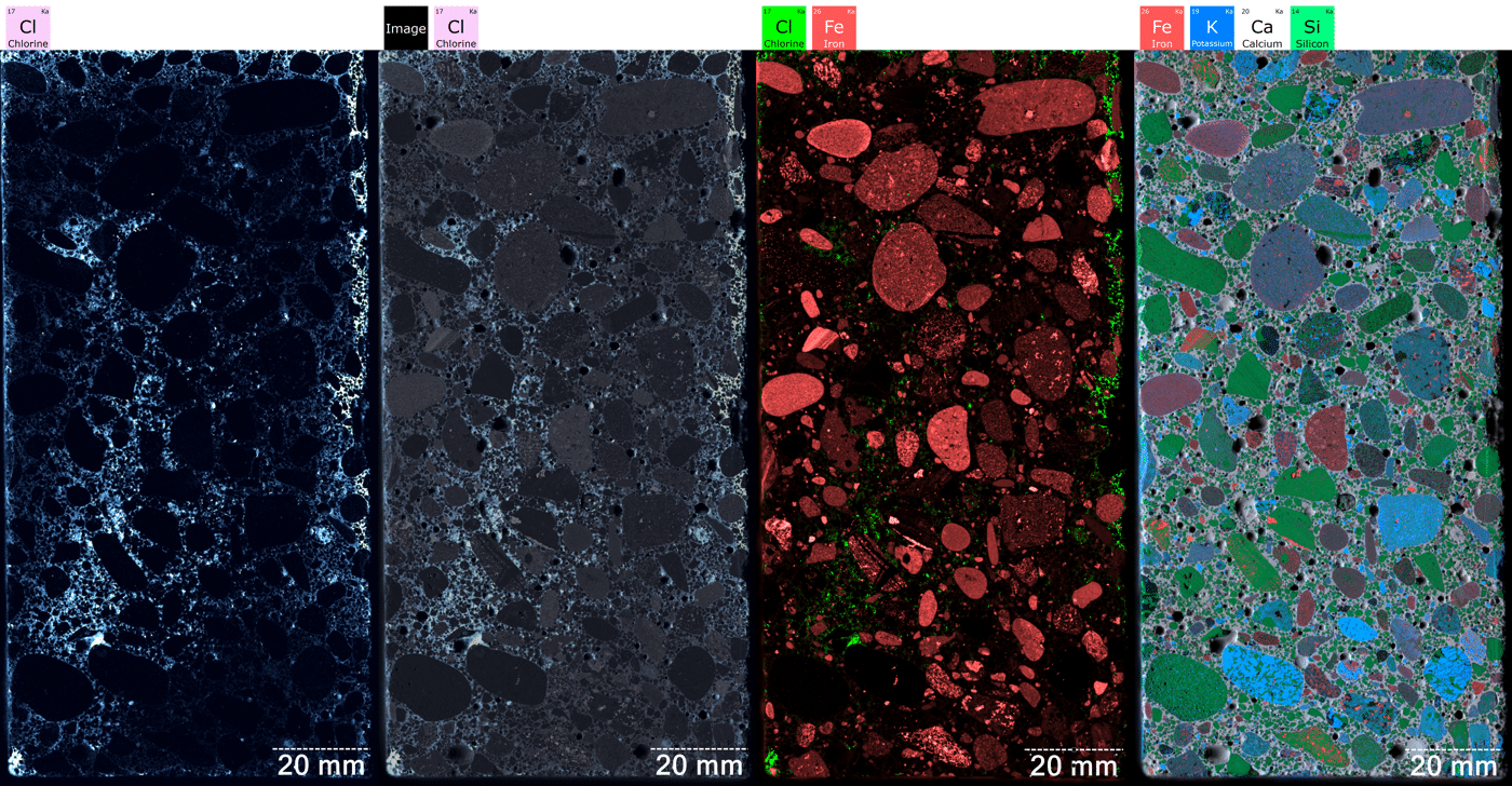
Figure 1. Large-area microXRF mapping of a concrete core for chloride-ingress assessment. The 77.70 × 151.5 mm cross-section was mapped in approximately two hours using 100 µm pixel spacing and a 5 ms dwell time per pixel. From left to right: chlorine map; chlorine/optical-image overlay; Fe–Cl elemental overlay; and Fe–K–Ca–Si elemental overlay. The chlorine maps visualize the spatial distribution of Cl relative to the concrete microstructure, while the multi-element views provide additional compositional contrast for differentiating aggregate and cementitious regions. Together, these views allow an analyst to evaluate chloride penetration through the cementitious matrix while navigating around aggregate rather than averaging aggregate-rich and paste-rich regions into the same profile.
From a Better Map to a Better Service-Life Assessment
The value of the map is not the image itself. It is the ability to extract a more defensible chloride-versus-depth relationship.
Instead of averaging all pixels across a horizontal band of the specimen, an analyst can identify cementitious regions and construct a profile from selected areas. Aggregate-rich pixels can be excluded or treated separately. Multiple paths can be evaluated to quantify local variability. Features that appear anomalous can be investigated rather than silently incorporated into a bulk average.
That opens several useful analytical paths. A chloride front can be compared with the measured reinforcement depth. Cracks can be examined independently to determine whether they have accelerated penetration. Repair materials and interfaces can be separated from the original concrete. Complementary elemental maps can help determine whether an apparent feature in the Cl profile is associated with ingress or simply with a change in material composition.
This does not make conventional laboratory chloride analysis obsolete. Standardized chemical methods remain essential wherever a specification, regulatory requirement, contractual test method, or historical dataset requires them. MicroXRF addresses a different limitation: conventional grinding necessarily sacrifices spatial context.
The Management Question Is Remaining Life, Not Simply Chloride Content
Infrastructure owners rarely collect cores because they want an elemental map. They collect them because a decision has to be made.
Can the structure remain in service? Is rehabilitation needed now or in ten years? Is chloride approaching the reinforcing steel? Is the observed deterioration localized or representative of a broader transport problem? Will a surface treatment or repair materially change the remaining service life?
Those decisions depend on a larger body of evidence: chloride exposure, cover depth, concrete quality, moisture, corrosion measurements, cracking, reinforcement condition, repair history, and service-life modeling. Chloride profiling is one piece of that assessment.
But when chloride data are used to characterize penetration through a heterogeneous composite material, understanding where the measurement came from can be just as important as understanding the measured concentration.
MicroXRF makes that distinction visible. Instead of forcing the chloride profile through an artificial straight line of paste, aggregate, voids, and interfaces, the analyst can follow the material pathway that matters. For infrastructure expected to remain in service for decades, that additional spatial context can improve the technical basis for the life-assessment conversation.
Want to see what this looks like on your concrete?IXRF Systems works with researchers, engineering laboratories, and materials specialists using microXRF to investigate concrete, cementitious materials, corrosion, and other heterogeneous materials. If you are evaluating chloride penetration, concrete cores, repair interfaces, or another durability problem, ask us how an Atlas Apex workflow could be configured for your samples and what information can realistically be extracted from the resulting maps. |
FAQ
How is chloride penetration measured in a concrete core?
Concrete is commonly sampled at successive depths and analyzed chemically to produce a chloride concentration profile. MicroXRF provides a spatial approach by mapping chlorine across the exposed core cross-section and extracting a depth profile from selected regions.
Why should aggregate be considered when measuring chloride penetration?
Environmental chloride is primarily associated with the cementitious matrix. If a sampled interval contains a high proportion of aggregate, that aggregate can dilute the measured chloride concentration. Some aggregates can also contain chloride of their own, further complicating bulk measurements.
Can microXRF measure chloride in concrete?
MicroXRF detects elemental chlorine and can map its distribution across a concrete cross-section. Quantitative chloride assessment requires suitable calibration, standards, sample preparation, and consideration of matrix effects.
Why is chloride penetration important to bridge service life?
When sufficient chloride reaches embedded reinforcing steel, it can contribute to loss of steel passivity and initiation of corrosion. Chloride concentration at reinforcement depth and the overall penetration profile therefore provide useful information for condition and remaining-service-life assessments.
What does microXRF add compared with conventional chloride profile grinding?
Conventional grinding averages everything within a sampled depth interval. MicroXRF preserves spatial information, allowing analysts to distinguish cementitious matrix from aggregate and identify cracks, interfaces, localized penetration pathways, and other heterogeneous features.
How quickly can a concrete core be mapped with microXRF?
Acquisition time depends on mapped area, pixel spacing, dwell time, detector configuration, and required sensitivity. In the example shown here, a 77.70 × 151.5 mm region was mapped in approximately two hours using 100 µm pixel spacing and 5 ms dwell per pixel.